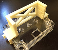
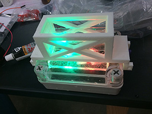
The MBL lightbox is a reusable, submersible, battery-powered narrow-spectrum LED illumination chamber with a 3D printed, environmentally exposed microscope slide holder that was designed as a low-cost solution for wave-length specific in situ enrichment of phototrophic microorganisms. The method selectively enriches for microorganisms that thrive under the provided light regime(s) but within the natural chemical environment of their native habitat. It was developed by Sebastian Kopf and Sean Kearney at the 2015 MBL Microbial Diversity summer course.
Materials
-
Enclosure: small, water proof project box
-
Acryl LED holder: laser cut the holder (single cut or 10 cuts on 12x12 inch plate) from 1/4 inch clear acryl (or 6mm acryl) if laser cutter available, otherwise a handsaw and 5mm drill bit work well too). Additional variations on the original design that are optimized for Tekon multi-well slides are available on GitHub (e.g. for 5mm 10 well slides, 4mm 24 well slides).
-
LEDs: relatively inexpensive 5mm LEDs in the visible and near infra-red are available from many different vendors (e.g. red, green, infra red, yellow). Very specific LEDs are available from Thorlabs but typically more expensive.
-
Microscope slide holder: 3D print the slide holder (STL files for larger half and smaller half) with any 3D printer (Makerbot is not ideal but tolerances are large enough that it will work). Additional variations on the original design are available on GitHub.
-
Glue: any water proof glue to attach the slide holder to the top of the enclosure
-
Resistors: a set of resistors comprising at least 22, 47, 100 and 220 Ohm
-
Microscopy slides: standard 1mm thick glass microscope slides - if frosted at one end, be mindful of LED placement
-
Battery pack: 4x AA battery holder and fully charged batteries
How to wire the LED circuit?
In this lightbox, we are using 4x AA batteries as the power source which provides a total of 4x 1.5V = 6V to drive our LEDs. To check which/how many LEDs we can power with this, we need to know the characteristic “forward voltage” of each LED (the approximate voltage drop across the LED). This voltage mostly depends on the color of the LED, for example red LEDs will typically have a forward voltage of 1.8-2.2 V while green LEDs might have 3.2-3.8 V. You can get the forward voltages from your LED datasheets (often denoted Vf) or estimate them from the typical values for the color in use (e.g. by looking up LED voltages on Wikipedia).
To maximize battery life, it is best to wire the LEDs in series. This makes it easy to limit total current and the circuit has only 3 components: 1) the battery pack to power the circuit (here 6V), 2) a resistor to control current flow, and 3) our LEDs. For an example circuit, we are including one red LED (forward voltage ~1.9V) and one green LED (forward voltage ~3.3V). To calculate which resistor to use, determine the leftover voltage in the circuit \(\left(V = 6\text{ V} - \sum V_f=6\text{ V} - 1.9\text{ V} - 3.3\text{ V} = 0.8\text{ V}\right)\), then decide what current to run at. Typically LEDs are rated at a maximum current of ~20mA but you can always run an LED with less current to reduce brightness and increase battery life. For the example circuit, we will aim to run at 10mA which is not maximum brightness but still quite a bit of light for bacterial phototrophs. Using Ohm’s law, the required resistor is \(R = V/I = 0.8\text{ V}/10\text{ mA} = 80\text{ Ohm}\). Resistors are usually available at specific values, a useful set that covers many scenarios for the light box includes 10, 22, 47, 100 and 220 Ohm resistors. Rounding up to the closest resistor for the example circuit means we’ll go with the 100 Ohm resistor.
Wire the circuit as illustrated in the diagram. Polarity matters for LEDs so the positive pole (usually red wire from the battery pack) has to connect to the anode of the LED, which is typically the longer lead (testing which one is the right one by swapping the connections will NOT hurt the LED, it just won’t light up). Make sure that the wiring is correct by turning on the battery pack, all LEDs in the circuit should light up (note that you will not see IR LEDs with the naked eye). If not, check for any loose wiring, accidental shorts (wires touching), correct polarity on the LEDs and sufficient battery charge. To keep connections tight and insulated from each other, twist wires together firmly and wrap with a layer of electrical tape or heat shrink.
How long can I run the lightbox for?
The total capacity (=lifetime) of a battery depends strongly on the material and the discharge rate. At low currents (<100mA), decent quality AA alkaline batteries, for example, typically have a capacity of ~2200 mAh (but they perform much worse at high discharge rates). This means that if you run your LED circuit at 10mA, your battery pack will last for 2200 mAh / 10 mA = 250 hours, or roughly 9 days! That is a pretty solid amount of time for in situ phototroph enrichments. If you want brighter LEDs and are running at 20mA, you will need to replace the batteries after ~4.5 days.
Additional advice on the circuit
-
Battery life: Since the nominal LED voltages are often only approximate, it is important to note that the exact current may vary from your theoretical calculations. This is not a problem unless you need precise estimates of the light output and/or expected battery life. If you have access to a multimeter, you can measure the actual current and if needed simply fine-tune your circuit by adjusting the resistor.
-
Resistor ratings: It is good practice to check the power rating of your resistor although this is unlikely to be a problem for the lightbox. The resistors linked/pictured in this tutorial are rated for 0.25 W (with 5% tolerance), which is far above what is necessary for this circuit even if running at maximum 25 mA \(\left( P=V\cdot I=0.8\text{ V}\cdot 25\text{ mA}=0.02\text{ W} \right)\).
- Higher voltage LEDs: If you want to drive several higher voltage LEDs (e.g. mutiple green, blue or UV), the 6V available from the 4 x AA battery pack may not be sufficient to drive them in series. You can either try to fit more batteries into the light box to increase total circuit voltage, use higher voltage batteries (be mindful of the trade-off in total capacity), or wire your LEDs in parallel instead of in series (adding the appropriate resistor for each parallel circuit) with the caveat that this circuit will consume more current so the batteries will not last as long. See an example of parallel wiring of two and two serial LEDs (blue and IR in series on the bottom, red and green on the top) on the right.
Assembly


-
Insert the LED holder into the lid of the enclosure so it is flush with the top of the lid. Depending on the precision of the laser cutter it might fit tightly enough on its own but if it loose in any way, fix in place with a little bit of tape, glue or silicone.
-
Add glue to the underside of the bigger part of the slide holder and attach it to the outside top of the enclosure lid such that it frames the LED cutouts in the acryl now attached to the underside of the lid. Do not us excess glue since it often expands and might interfere with the microscope slide position right on top of the lid. Let glue set to make sure the bigger side of the slide holder is firmly attached (depending on the glue may take several hours or overnight). Do NOT glue the smaller side of the slide holder!
-
Insert the LEDs with the assembled circuit into the LED holes in the acryl. Fix LEDs in place with electrical tape or silicone. Tape is not as robust over time but has the advantage that the circuit is exchangeable later on for different LED combinations. Add battery pack into the bottom of the enclosure, if too loose can be fixed lightly into place with double sided tape.
-
Close lightbox, add microscope slides (if excess glue interferes, carefully scrape away obstructing glue with a knife) and add smaller side of slide holder (hold in place with zip tie or large safety pin through the holes on each side of the holder). Turn LEDs on, screw lid into place (do not overtighten, the screws can crack) and test assembly in a water bucket in the lab to make sure no water intrudes. Ready to deploy! (fishing line, weights and bobber help with deployment at the right depth).


